
Coupling Decoupling Networks for Transients
Conducting full-compliance immunity tests like burst and surge, suitable accessories are required besides the disturbance generator: calibration accessories, in order to perform periodical verification / calibration as required, coupling decoupling networks, in some cases coupling clamps or capacitors, etc. This article will focus on coupling decoupling networks for burst and surge immunity tests, as described in IEC 61000-4-4 and IEC 61000-4-5.
What is a coupling decoupling network?
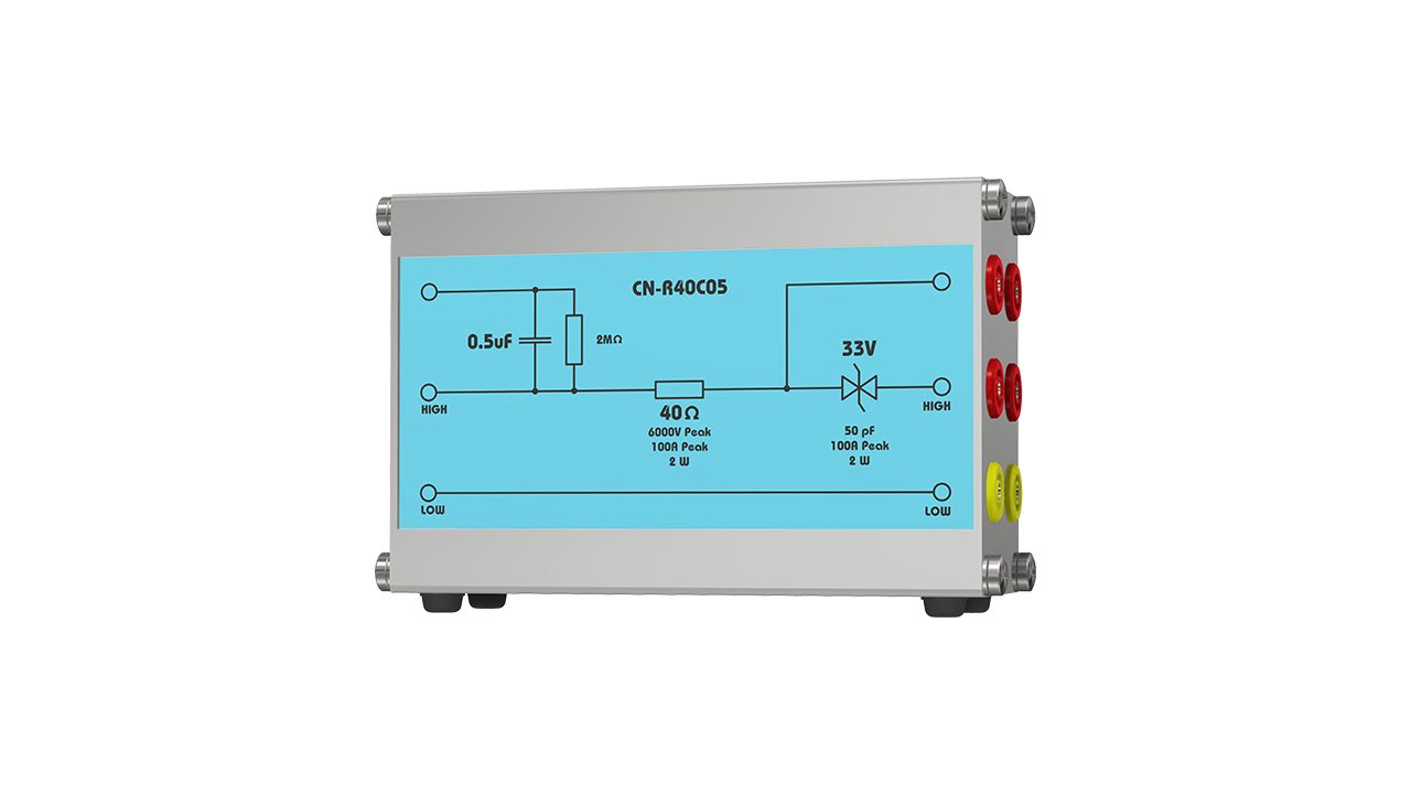
A coupling decoupling network (CDN) is a device utilized to superpose disturbances on power, communication, control or similar lines connected to an Equipment Under Test (EUT) port, while ensuring that disturbances are applied only to EUT and not to power sources or Auxiliary Equipment (AE). Such a device is needed, since IEC conducted immunity tests have to be performed while EUT is powered and performs its functions. A basic representation of a CDN for applying surge disturbances on power lines can be observed bellow. The principle is similar for applying burst disturbances on power lines.

With the help of a CDN, the disturbance coming from the generator is directed towards the EUT only: the coupling network allows the disturbance to pass toward EUT supply line, but prevents the EUT power from entering the generator. The decoupling network allows EUT power to pass towards EUT, but prevents the disturbance coming from generator to reach the power supply or AE.
Hence, a coupling decoupling network allows the application of disturbances to powered EUT lines and thus efficiently simulate the occurrence of disturbances in the power network, as if they occurred due to phenomena typical to these environments (power networks, communication lines, etc.).
What is coupling path?
In the example provided above, disturbances are applied to EUT supply port / lines by means of a CDN. This explanation is provided specifically for surge test (IEC 61000-4-5) and will be extended to other types of disturbances subsequently. It is thus assumed that in the diagram above, the power port where the CDN has been connected is single-phase and consists of three lines: Line (L), Neutral (N) and PE (Protective Earth). Since the disturbance is applied between two points, or lines, the possible coupling paths are: L to N, L to PE and N to PE. A coupling path represents a specific selection to connect generator’s output terminals (High and Low) to EUT’s port. When connecting the High and Low of surge generator to L and N lines, the coupling is considered a differential mode coupling. When the High and Low of generator are connected to L and PE respectively, or N and PE, the coupling is common mode. As a rule, whenever the Low terminal of the generator is connected to PE (or ground plate) the coupling is considered a common mode one. When performing a complete surge test as per IEC 61000-4-5, both differential mode (L to N) and common mode (L to PE and N to PE) are selected successively. These coupling modes are presented in the diagram below.
IEC 61010-1 | Safety requirements for electrical equipment for measurement, control, and laboratory use - Part 1: General requirements |
EN 50121-3-2 | Railway applications - Electromagnetic compatibility - Part 3-2: Rolling stock - Apparatus |
EN 50155 | Railway applications. Rolling stock. Electronic equipment |
IEC 61980-1 | Electric vehicle wireless power transfer (WPT) systems - Part 1: General requirements |
IEC 61000-4-4 | Electromagnetic compatibility (EMC) - Part 4-4: Testing and measurement techniques |
IEC 61000-4-5 | Electromagnetic compatibility (EMC) - Part 4-5: Testing and measurement techniques - Surge immunity test |
IEC 61000-4-12 | Electromagnetic Compatibility (EMC) - Part 4-12: Testing and measurement techniques - Ring wave immunity test |
 | Direct Coupling Network for Railway Applications |
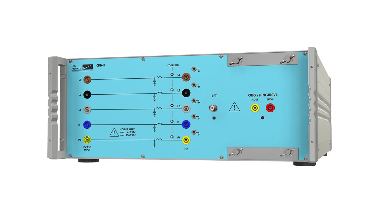
 | EFT, Surge & Ring wave automatic 3-phase CDN for power supply lines. EUT max 690Vac / 1500Vdc / 63A per phase | |
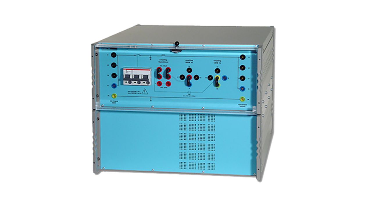
 | EFT, Surge & Ring wave automatic 3-phase CDN for power supply lines. EUT max 690Vac / 1500Vdc / 200A per phase | |
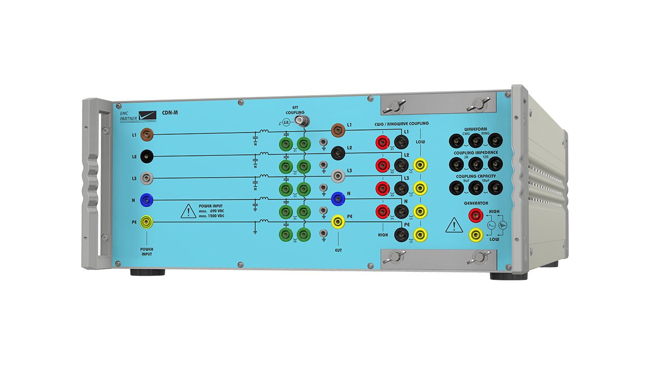
 | EFT, Surge & Ring wave automatic 3-phase CDN for power supply lines. EUT max 690Vac / 1500Vdc / 125A per phase | |
 | EFT, Surge & Ring wave automatic 3-phase CDN for power supply lines. EUT max 690Vac / 1500Vdc / 32A per phase | |
| EFT, Surge & Ring wave automatic 3-phase CDN for power supply lines. EUT max 690Vac / 1500Vdc / 125A per phase | |
 | Three phase CDN for MIG1206 | |
 | Automatic 3-Phase CDN up to 32A / 8kV for EFT, Surge and Ringwave (690V) |